ChatGPT (GPT Image)
Prompt 1
show prompt
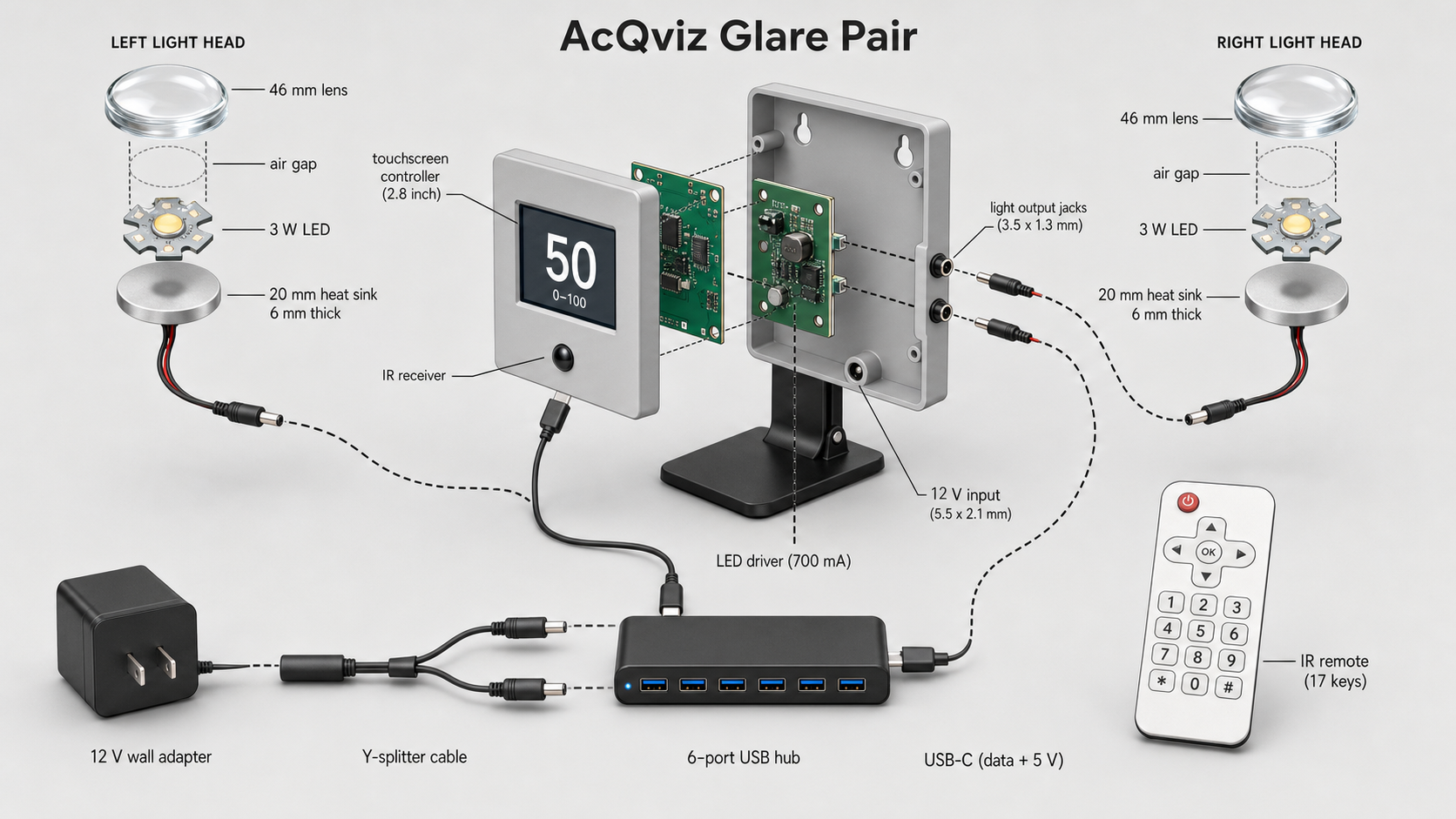
A precise isometric exploded-view technical illustration of a medical LED glare-testing product called "AcQviz Glare Pair", drawn like a page from a premium product manual: consistent isometric angle, neutral light-gray studio background, soft shadows, fine dashed assembly axes, thin leader lines to small clean sans-serif callout labels. Use EXACTLY this label copy, spelled precisely: "AcQviz Glare Pair" (title), "LEFT LIGHT HEAD", "RIGHT LIGHT HEAD", "46 mm lens", "air gap", "3 W LED", "20 mm heat sink", "touchscreen controller (2.8 inch)", "IR receiver", "LED driver (700 mA)", "light output jacks (3.5 x 1.3 mm)", "12 V input (5.5 x 2.1 mm)", "USB-C (data + 5 V)", "12 V wall adapter", "Y-splitter cable", "6-port USB hub", "IR remote (17 keys)". CENTER: a small light-gray wall-mountable control box on a black desk stand, exploded front-to-back into: front bezel with a 2.8-inch touchscreen showing ONLY a large two-digit numeral "50" with a small "0–100" scale caption beneath it; below the screen a small dark IR receiver dome; behind the bezel a controller PCB; behind that a single green LED driver PCB; the rear shell has two keyhole wall-mount slots. On the box's bottom face: one threaded 5.5 x 2.1 mm barrel jack. On the box's right side: two small 3.5 x 1.3 mm panel-mount jacks, one above the other. LEFT AND RIGHT: two identical cylindrical light heads, each exploded front-to-back into: a 46 mm plano-convex clear glass lens, an air gap, a 3-watt warm-white LED chip on a 20 mm star-shaped aluminum PCB, and a SMALL LOW-PROFILE round aluminum heat-sink puck only 6 mm thick (a thin flat disc, NOT a tall finned cylinder). Each light head has a thin black two-wire pigtail cable ending in a small barrel plug. POWER ROUTING — draw these connections exactly, with dashed routing lines: BOTH light-head pigtails curve to the SAME two side jacks on the control box (left head's plug into one jack, right head's plug into the other). Inside the box, both jacks are wired to the single green LED driver PCB — one driver powers both lights. The driver PCB is wired to the bottom 12 V barrel jack. Along the bottom of the image, left to right: a black 12 V wall adapter connects into a Y-splitter cable with one female and two male barrel plugs; the first splitter leg runs to a black 6-port USB hub; from the hub a USB-C cable runs UP and connects ONLY to the touchscreen controller board, never to the lights; the second splitter leg runs to the 12 V barrel jack on the bottom of the control box. FOREGROUND: a small white infrared remote with exactly this layout: a power button at top, a directional pad with up, down, left, right arrow keys around a center "OK" key, and a 3 x 4 grid of digit keys 0 through 9 with "*" and "#" — no color-temperature buttons, no timer buttons. Uncluttered, precise, high-end product-manual aesthetic with muted color accents.
 #1